Designing for 3D Printing: Professional Tips
Learn how to design parts that are perfectly 3D printable. From wall thickness to overhangs - the most important design rules for successful prints explained.
Dennis
3Dennis
Contents
A brilliant design on your screen doesn’t automatically mean a successful 3D print. The technology has its own rules and limitations, and the best designers account for these from the start.
At 3Dennis, we review customer designs daily. Some are directly printable, others require modifications. In this article, we share the knowledge we’ve built up, so you can design correctly right away.
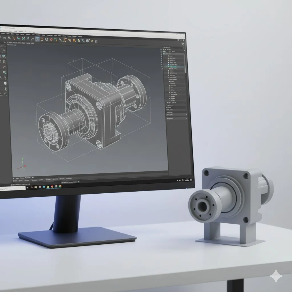
Design for Manufacturing: a different mindset
With traditional manufacturing, you think in terms of removing material: milling, turning, drilling. With 3D printing, you build layer by layer. This fundamental difference requires a different design approach.
The good news is that 3D printing makes complexity free. Internal structures, organic shapes, and integrated functionality cost no more than simple shapes. But you must stay within the physical possibilities of the process.
The most important design rules
Minimum wall thickness
Walls that are too thin don’t print well or are too fragile for practical use. The absolute minimum wall thickness depends on your nozzle, but as a rule of thumb:
- Minimum 1.2mm for structural walls
- Preferably 1.6mm or more for rigidity
- 0.8mm can work for non-load-bearing visual elements
Thinner than 0.8mm is technically sometimes possible, but rarely practical. The wall becomes too flexible and can break easily.
Overhangs and the 45-degree rule
3D printers can’t print in mid-air. Each layer must rest on something - the previous layer or support material. Overhangs up to 45 degrees usually print without problems; steeper requires support.
How can you work smartly with this?
Rotate your model. A part that has 60-degree overhangs on its side might have no overhangs at all if you rotate it 90 degrees. Think about optimal print orientation.
Add chamfers. A 45-degree bevel under a protruding part eliminates the need for support and makes the model stronger.
Split complex shapes. Sometimes it’s better to split a complex part into two simple pieces that you join later.
Bridges: horizontal spans
Horizontal bridges between two support points can be printed without support up to a certain length. Most printers can bridge 20-30mm, depending on material and settings.
Longer bridges sag in the middle and don’t give good results. Design an intermediate support point instead or use support for long spans.
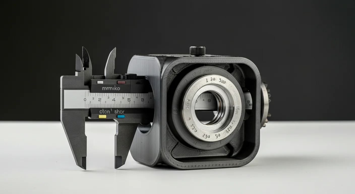
Tolerances for moving and fitting parts
When two parts need to fit together or move past each other, you need clearance. 3D printed parts never come out exactly on size - there’s always some variation.
For a loose fit (parts that slide together easily) calculate with 0.3-0.5mm clearance per side. For a tight fit (light friction) 0.1-0.2mm is sufficient.
Threads require extra attention. Printed internal threads usually don’t work well - use heat-set inserts instead or tap the thread after printing.
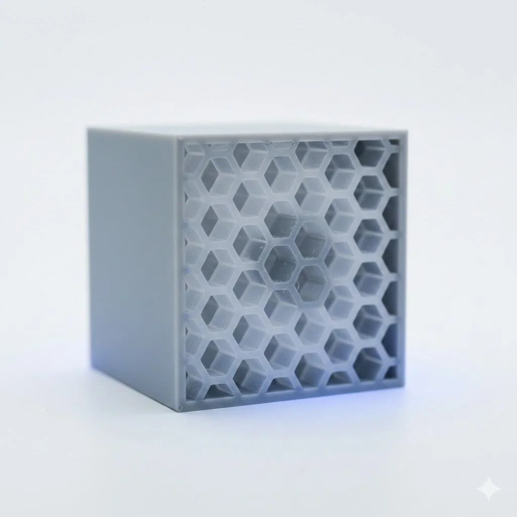
Hollow versus solid
A solid design is rarely necessary and wastes material. Use your CAD software to hollow out parts, or rely on your slicer’s infill settings.
When hollowing yourself: ensure sufficient wall thickness (minimum 2-3mm) and consider a small hole to let trapped air escape during printing.
Common design mistakes
Too small details
Fine details smaller than 0.5mm get lost or print unreliably. Text, logos, and decorations must be large enough to print. Embossed text at minimum 1mm deep and 3mm tall usually works.
Sharp internal corners
Sharp 90-degree internal corners are stress concentrators and can cause cracking. Add a small radius (0.5-1mm) to internal corners for a stronger part.
Inaccessible cavities
If your design contains completely closed cavities, support cannot be removed. Always ensure an opening through which support or loose powder can escape, even if it’s a small hole.
Extremely thin cylinders
Thin pins and cylinders are fragile and difficult to print. Below 3mm diameter they become problematic. Consider conical shapes or reinforcements at the base.
Optimizing for strength
Layer direction determines your print’s strength. Layers are strong in their own plane but can separate relatively easily.
Design parts so the primary load falls in the plane of the layers, not perpendicular to them. This may mean printing a part in a different orientation than seems intuitively logical.
For critical connections, you can add reinforcements: thicker walls, ribs, or gussets that distribute forces over a larger surface.
Software tips
Use a suitable tool
For mechanical parts, parametric CAD programs like Fusion 360, OnShape, or SolidWorks are ideal. You can enter exact dimensions and easily adjust later.
For organic shapes and art, mesh-based tools like Blender or ZBrush are better, though these require more post-processing for printability.
Export correctly
Export your model as STL or 3MF with sufficient resolution. Too low mesh resolution gives facets on curved surfaces. For most parts, a tolerance of 0.01-0.05mm is sufficient.
Check your model
Use tools like Meshmixer or your slicer’s built-in analysis to detect problems. Non-manifold geometry, reversed normals, and overlapping faces can cause print problems.
When to get help
Not every design is directly printable, and that’s no shame. Complex shapes require experience to optimize for 3D printing.
At 3Dennis, we offer design reviews and modifications. Send your design and we’ll give feedback on printability, suggestions for improvements, and a realistic estimate of the end result.
Contact us to have your design reviewed, or ask about our design services if you’re starting from scratch.
Keep reading
3D Printing Tolerances and Accuracy: What to Expect
How accurate is FDM 3D printing? Learn typical tolerances, factors affecting precision, and how to design parts for the best possible fit.
Choosing the Right Infill Percentage: A Complete Guide
How much infill does your 3D print really need? Learn when to use 20%, 50%, or 100% infill for optimal strength, weight, and print time.

Common 3D Printing Mistakes and How to Avoid Them
Learn from others' mistakes: the most common 3D printing problems and how to prevent them. From warping to layer adhesion - practical solutions explained.
Need help with your project?
Contact us for custom 3D prints or B2B services.